一、SPI接口概述
字数
2170 字
阅读时间
11 分钟
1、概述
SPI接口简单,时钟可达100M以上,用于串行通信。存储器,温度传感器,压力传感器,模拟转换器,实时时钟,显示器以及任何支持串行模式的 SD 卡。 一些 ADC 比如 AD7606 也可以用 SPI 接口实现通信。


2、SPI总线协议介绍
2.1 技术性能
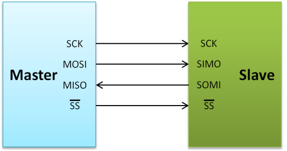
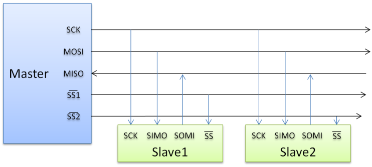
SPI,全双工三线同步串行外围解耦,主从模式,支持单主多从。Master控制时钟,高位在前,低位在后。两根单向数据线,全双工,实际应用速率可达机Mbps。 
2.2 接口定义:
- MOSI:串行输出数据线,主器件数据输出,从器件数据输入
- MISO:串行输入数据线,主器件数据输入,从器件数据输出
- SCLK:时钟线,由主器件产生
- /SS:片选,从器件使能信号,由主器件控制
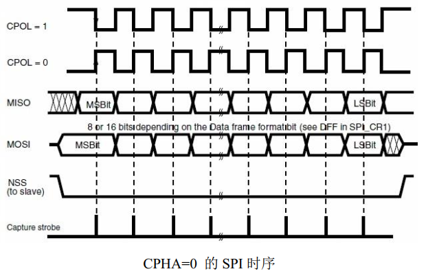
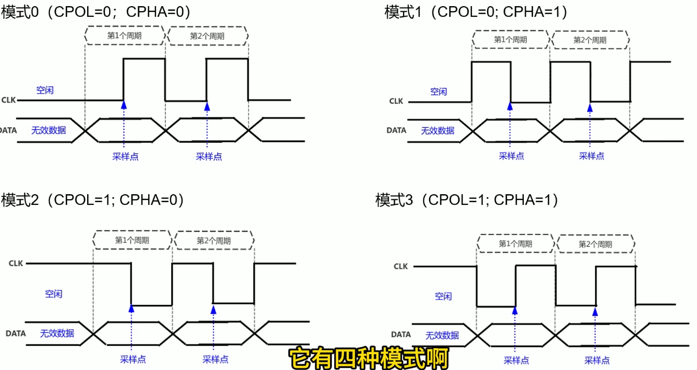
2.3 时钟极性和时钟相位:
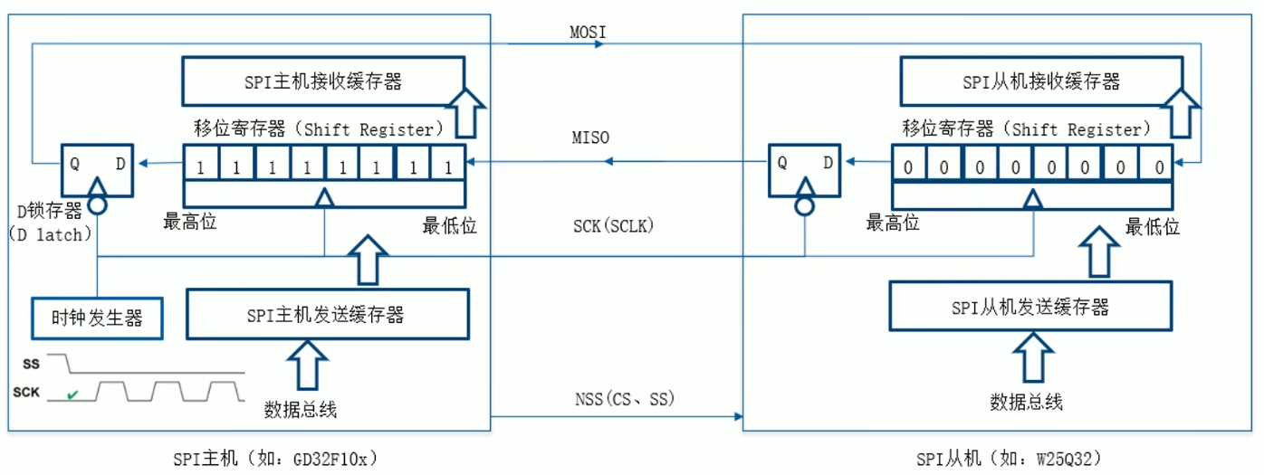
SPI数据传输在串行同步时钟信号(Serial Clock,SCK)控制下进行。一边控制主机位移寄存器,一边通过从机的SCK控制从机的移位寄存器,保证主机与从机的数据交换是同步进行的。
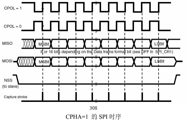
SCK可设置为不同极性(Clock Polarity , CPOL)和相位(Clock Phase , CPHA)
- CPOL:为0,SCK空闲时为低;为1,SCK空闲时为高。
- CPHA:为1,在SCK的二个跳变沿采样,CPOL为0,取下降沿,CPOL为1,取上升沿;为0,第一个跳变沿采样,CPOL为0,取下降沿,CPOL为1,取上升沿。


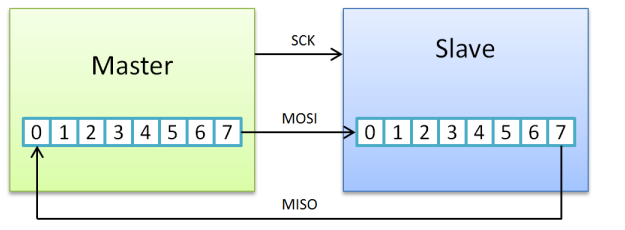
2.4 数据传输
一个 SPI 时钟周期内:
- 主机通过 MOSI 线发送 1 位数据,从机通过该线读取这 1 位数据
- 从机通过 MISO 线发送 1 位数据,主机通过该线读取这 1 位数据

 主机内的时钟发生器,同时影响主机和从机。
 主机内的时钟发生器,同时影响主机和从机。
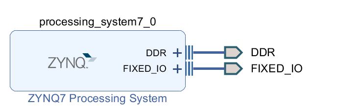
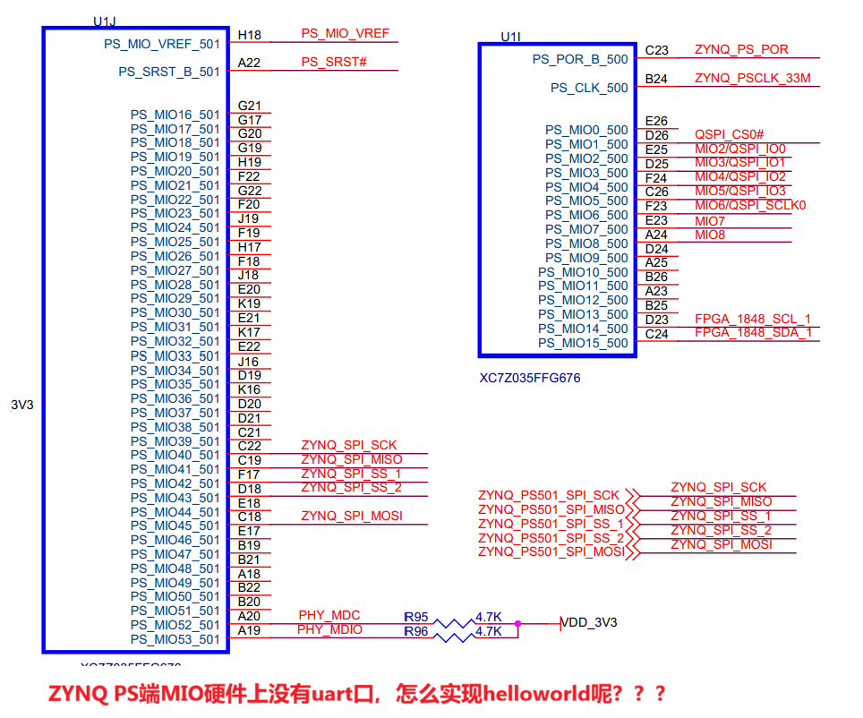
二、首先先连上PS,内部打印helloworld
先关闭所有功能,包括中断、uart都关了 
 sdk里debug as,run
c
#include "xil_printf.h"
#include "sleep.h"
int main(void)
{
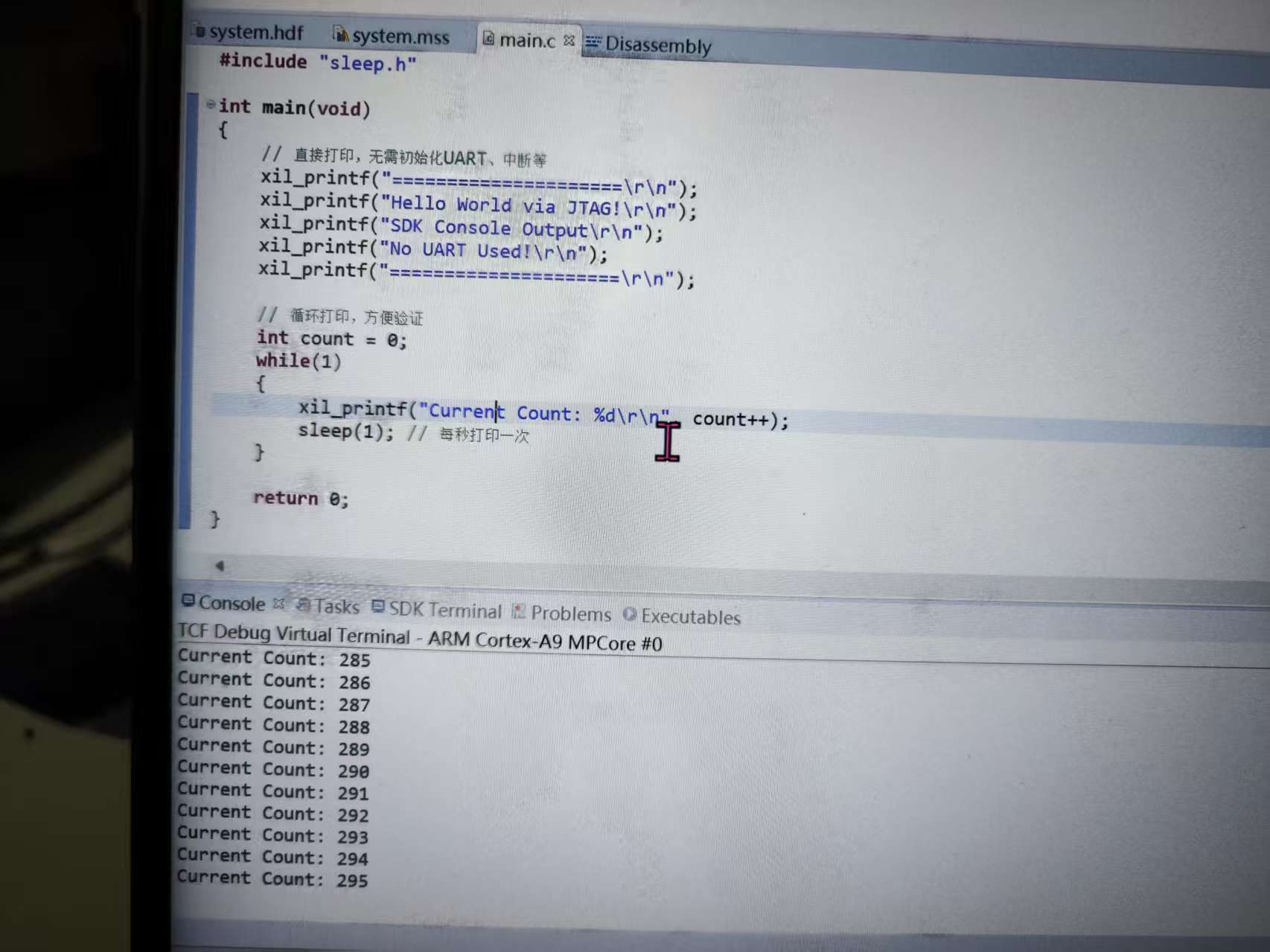
// 直接打印,无需初始化UART、中断等
xil_printf("=====================\r\n");
xil_printf("Hello World via JTAG!\r\n");
xil_printf("SDK Console Output\r\n");
xil_printf("No UART Used!\r\n");
xil_printf("=====================\r\n");
// 循环打印,方便验证
int count = 0;
while(1)
{
xil_printf("Current Count: %d\r\n", count++);
sleep(1); // 每秒打印一次
}
return 0;
}
三、用AXI-SPI进行测试
3.1 PL部分
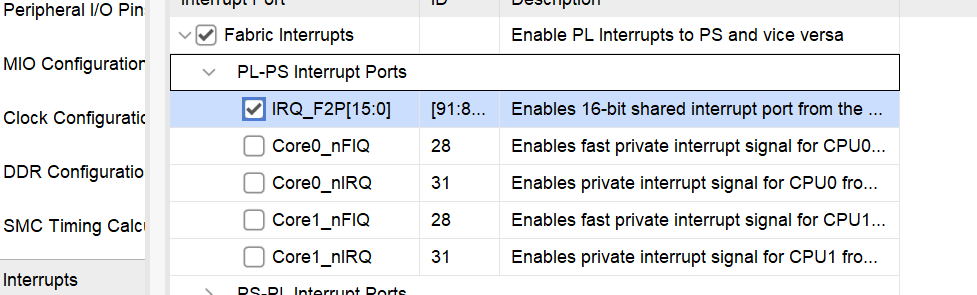
搭建soc 中断设置 
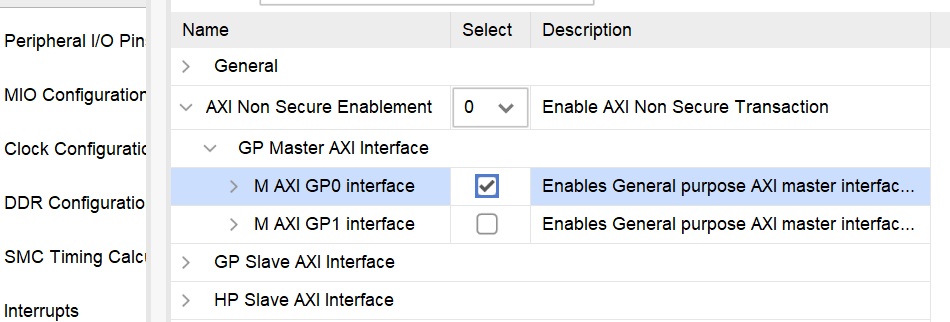
 设置 GP Master 接口
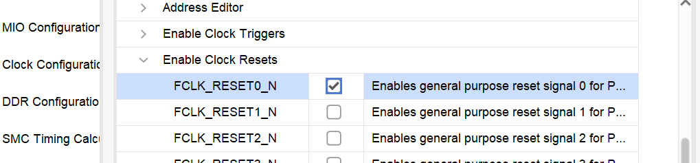
 设置复位输出
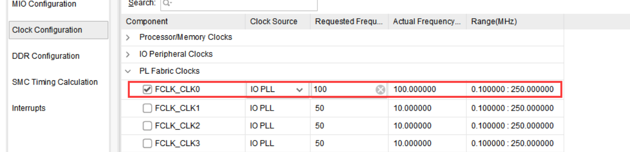
 设置 PL 时钟
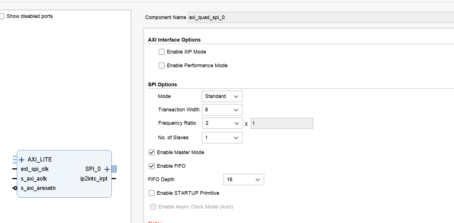
 AXI-SPI IP
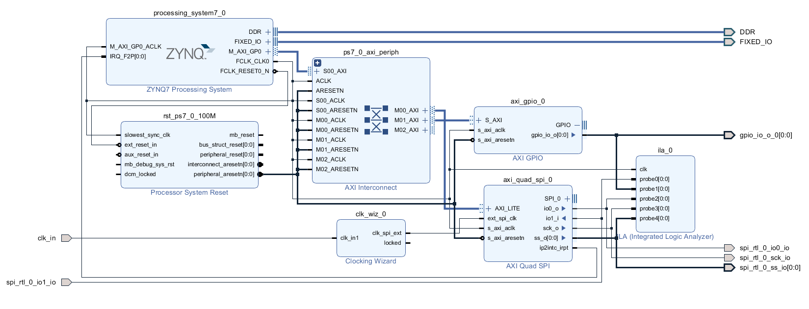
 最终形态
最终形态 
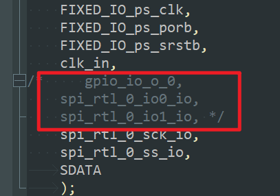
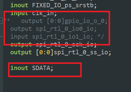
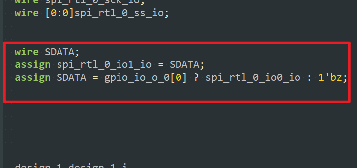
 为了满足三态,顶层应该这样修改


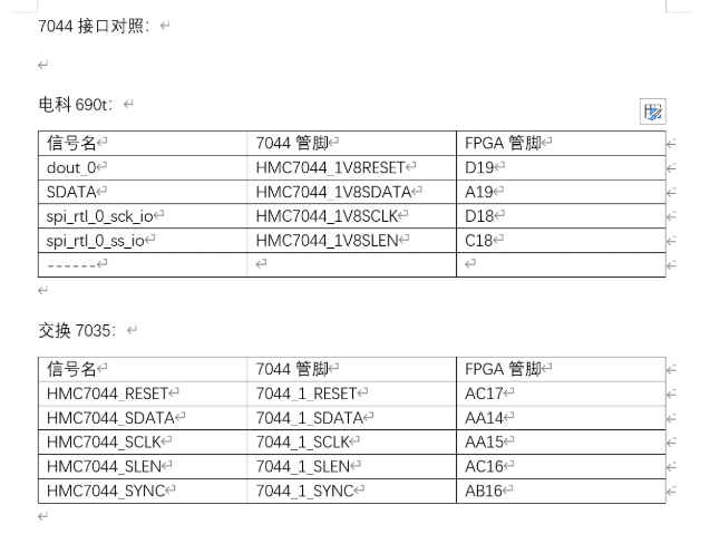
 引脚分配对应关系
3.2 PS部分
下面代码为不断往SPI里写入0x55的程序 运行时遇到问题,打断点定位到这个地方 
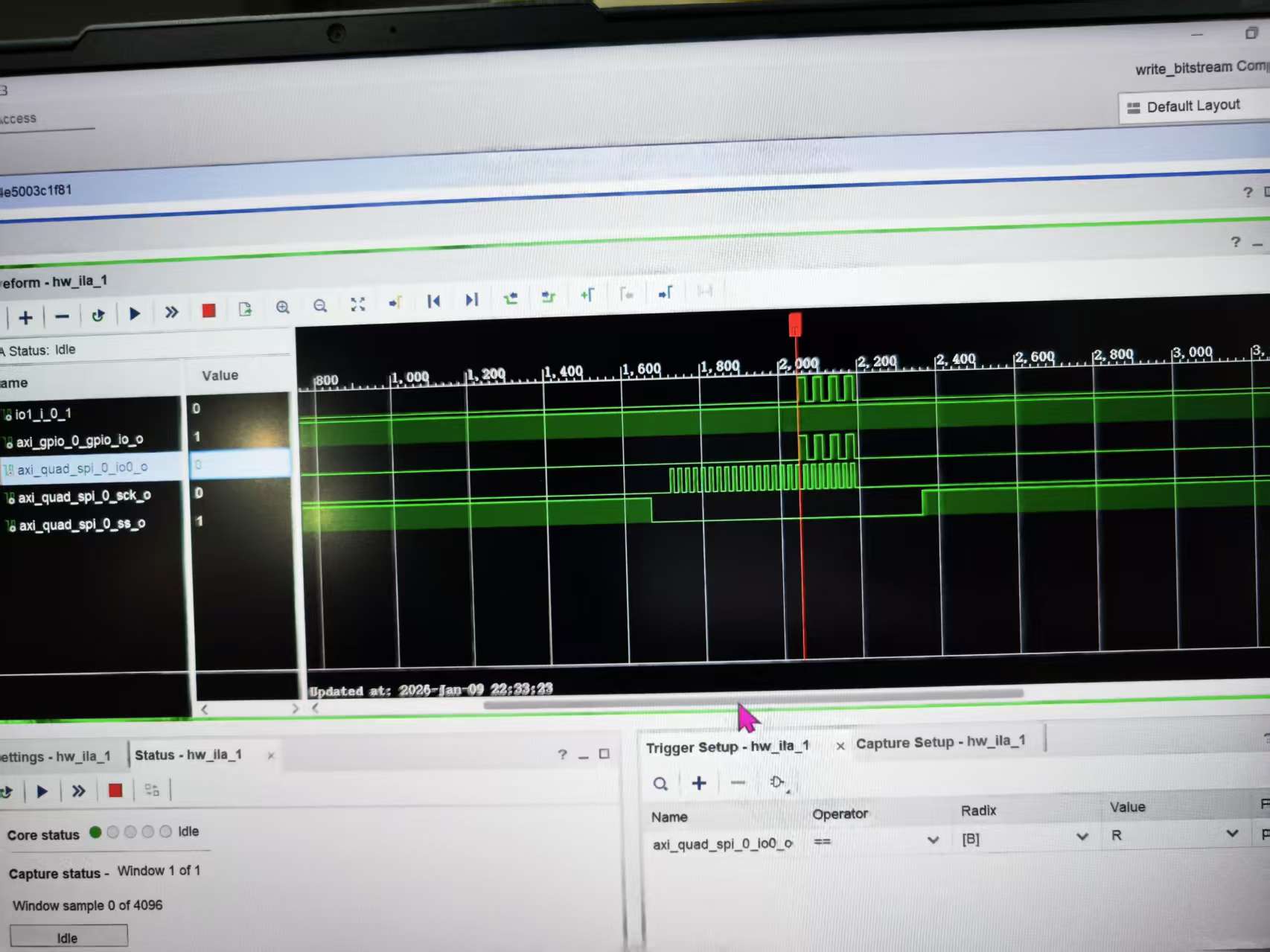
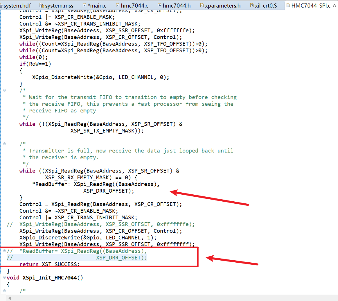 大致错误是因为写入了一遍以后读了一边,此时寄存器里已经没有了。 但是下面又对空的寄存器读了一遍,所以导致程序报错 把下面的红框部分注释掉以后,就不在报错了,程序正常运行 最后用过lia抓波形成功写入0x55
c
/***************************** Include Files **********************************/
#include <stdio.h>
#include <stdbool.h>
//#include "HMC7044_SPI.h"
#include "hmc7044.h"						// HMC7044芯片的驱动头文件
#include "xparameters.h"					// SDK自动生成的硬件参数(SPI/GPIO设备ID、基地址等)
#include "xspi_l.h"							// Xilinx SPI底层驱动
#include "xspi.h"							// Xilinx SPI高层驱动
/************************** Constant Definitions ******************************/

/*
 * The following constants map to the XPAR parameters created in the
 * xparameters.h file. They are defined here such that a user can easily
 * change all the needed parameters in one place.
 */


/**************************** Type Definitions ********************************/


/***************** Macros (Inline Functions) Definitions **********************/


struct hmc7044_dev* hmc7044_device;			// HMC7044设备实例指针

struct hmc7044_chan_spec chan_spec[14] = {
	/* OUTPUT0 */
	{
		.disable = 0,						//disable:0 = 启用通道,1 = 禁用通道
		.num = 0,
		.divider = 16,						//divider:分频系数(比如 OUTPUT1 的 256 表示输入时钟分频 256 后输出)
		.driver_mode = 2,					//输出驱动模式(2 是芯片指定的模式值)
		.coarse_delay = 16					//粗延时配置(调整输出时钟相位)
		//.driver_impedance = 1
	},
	/* OUTPUT1 */
	{
		.disable = 0,
		.num = 1,
		.divider = 256,
		.driver_mode = 2,
		.start_up_mode_dynamic_enable = true,
		.high_performance_mode_dis = true,
		.output_control0_rb4_enable = true,
		.force_mute_enable = true,
		//.driver_impedance = 1
	},
	/* OUTPUT2 */
	{
		.disable = 0,
		.num = 2,
		.divider = 16,
		.driver_mode = 2,
		.coarse_delay = 15
		//.driver_impedance = 1
	},
	/* OUTPUT3 */
	{
		.disable = 0,
		.num =3,
		.divider = 256,
		.driver_mode = 2,
		.start_up_mode_dynamic_enable = true,
		.high_performance_mode_dis = true,
		.output_control0_rb4_enable = true,
		.force_mute_enable = true,
		//.driver_impedance = 1
	},
	/* OUTPUT4 */
	{
		.disable = 1,
		.num = 4,
		.divider = 16,
		.driver_mode = 2,
		.coarse_delay = 15
	},
	/* OUTPUT5 */
	{
		.disable = 1,
		.num = 5,
		.divider = 256,
		.driver_mode = 2,
		.start_up_mode_dynamic_enable = true,
		.high_performance_mode_dis = true,
		.output_control0_rb4_enable = true,
		.force_mute_enable = true,
		//.driver_impedance = 1
	},
	/* OUTPUT6 */
	{
		.disable = 1,
		.num = 6,
		.divider = 16,
		.driver_mode = 2,
		.coarse_delay = 16
	},
	/* OUTPUT7 */
	{
		.disable = 1,
		.num = 7,
		.divider = 128,
		.driver_mode = 2,
		.start_up_mode_dynamic_enable = true,
		.high_performance_mode_dis = true,
		.output_control0_rb4_enable = true,
		.force_mute_enable = true,
		//.driver_impedance = 1
	},
	/* OUTPUT8 */
	{
		.disable = 0,
		.num = 8,
		.divider = 16,
		.driver_mode = 2,
		.coarse_delay = 16
	},
	/* OUTPUT9 */
	{
		.disable = 0,
		.num = 9,
		.divider = 16,
		.driver_mode = 2,
		.coarse_delay = 16
		//.driver_impedance = 1
	},
	/* OUTPUT10 */
	{
		.disable = 1,
		.num = 10,
		.divider = 16,
		.driver_mode = 2,
		.coarse_delay = 15
	},
	/* OUTPUT11 */
	{
		.disable = 1,
		.num = 11,
		.divider = 128,
		.driver_mode = 2,
		.start_up_mode_dynamic_enable = true,
		.high_performance_mode_dis = true,
		.output_control0_rb4_enable = true,
		.force_mute_enable = true,
		//.driver_impedance = 1
	},
	/* OUTPUT12 */
	{
		.disable = 0,
		.num = 12,
		.divider = 16,
		.driver_mode = 2,
		.coarse_delay = 16
	},
	/* OUTPUT13 */
	{
		.disable = 0,
		.num = 13,
		.divider = 256,
		.driver_mode = 2,
		.start_up_mode_dynamic_enable = true,
		.high_performance_mode_dis = true,
		.output_control0_rb4_enable = true,
		.force_mute_enable = true,
	}
	};


struct hmc7044_init_param example_hmc7044_param = {						//HMC7044 的核心初始化配置,决定了芯片的时钟输出频率、GPIO 行为、PLL 参数等,必须和硬件手册匹配。
		//.spi_init = &example_spi_init_param,
		.clkin_freq = {163680000, 163680000, 163680000, 163680000},		// 输入时钟频率(4路参考时钟,均为163.68MHz)
		.vcxo_freq = 163680000,											// VCXO晶振频率
		.pll2_freq = 2618880000,										// PLL2输出频率(2.61888GHz)
		//.pll1_loop_bw = 50,
		.pll1_loop_bw = 20,												// PLL1环路带宽(20Hz)
		.sysref_timer_div = 3840,
		.in_buf_mode = {0x07, 0x07, 0x07, 0x07, 0x07},
		.gpi_ctrl = {0x00, 0x00, 0x00, 0x11},							// GPI引脚控制配置
		.gpo_ctrl = {0x1f, 0x2b, 0x00, 0x00},							// GPO引脚控制配置
		.num_channels = 14, 											// 通道总数(对应上面的14路)
		.pll1_ref_prio_ctrl = 0x93,
		.sync_pin_mode = 0x1,
		.high_performance_mode_clock_dist_en = true,
		.high_performance_mode_pll_vco_en = true,
		.pulse_gen_mode = 0x0,
		.channels = chan_spec											// 关联通道参数数组
};

/************************** Function Prototypes *******************************/
int SPI_Write_Test(u32 base_addr, u8 reg_addr, u8 data);


/************************** Variable Definitions ******************************/
int main(void)
{
	int Status;
	int a=1;

	// 1. 定义寄存器读写缓冲区
/*
	u8  ReadReg_0x7D[3]={0X80 , 0X7d ,0x00};			// 读0x7D寄存器的指令(SPI帧格式)
	u8  ReadReg_0x70[3]={0x80 , 0x70 ,0x00};
	u8  WriteReg_0x70[3]={0x00 , 0x70 , 0xff};			// 写0x70寄存器(值0xff)
	u8  WriteReg_0x71[3]={0x00 , 0x71 , 0x1f};
	u8  ReadReg_0x71[3]={0x80 , 0x71 , 0x1f};
	u8  ReadReg_0x7C[3]={0X80 , 0X7C ,0x00};

	u8  ReadBuffer=0;									// 存储寄存器读取结果
*/

	// 2. 初始化HMC7044的SPI接口
	XSpi_Init_HMC7044();								// 自定义SPI初始化函数


	// 3. 初始化HMC7044芯片(传入配置参数)
	Status = hmc7044_init(&hmc7044_device, &example_hmc7044_param);
    if(Status != 0) { 									// 检查初始化结果,方便调试
        while(1); 										// 初始化失败则卡死,便于定位
    }
	usleep(55000);										// 等待55ms,让芯片完成初始化(PLL锁定、配置生效)


 	// 4. 死循环:持续读写HMC7044寄存器
	while(a==1)
	{
        // 写测试:往TEST_REG_ADDR寄存器写入0x55
        SPI_Write_Test(SPI_BASEADDR, 0x00, 0x55);
        // 延时50ms(1ms=1000微秒,50ms=50000微秒)
        usleep(50000);


/*
		XSpi_HMC7044_RoW(1,SPI_BASEADDR ,ReadReg_0x70 ,&ReadBuffer);	// 读0x70寄存器 → 写0x70寄存器(值0xff)→ 再读0x70寄存器(验证写入)
		usleep(5000);
		XSpi_HMC7044_RoW(0,SPI_BASEADDR ,WriteReg_0x70 ,&ReadBuffer);
		usleep(5000);
		XSpi_HMC7044_RoW(0,SPI_BASEADDR ,WriteReg_0x70 ,&ReadBuffer);
		usleep(5000);
		XSpi_HMC7044_RoW(1,SPI_BASEADDR ,ReadReg_0x70 ,&ReadBuffer);
		usleep(5000);

		XSpi_HMC7044_RoW(1,SPI_BASEADDR ,ReadReg_0x71 ,&ReadBuffer);
		usleep(5000);
		XSpi_HMC7044_RoW(0,SPI_BASEADDR ,WriteReg_0x71 ,&ReadBuffer);
		usleep(5000);
		XSpi_HMC7044_RoW(0,SPI_BASEADDR ,WriteReg_0x71 ,&ReadBuffer);
		usleep(5000);
		XSpi_HMC7044_RoW(1,SPI_BASEADDR ,ReadReg_0x71 ,&ReadBuffer);
		usleep(5000);

		XSpi_HMC7044_RoW(1,SPI_BASEADDR ,ReadReg_0x7D ,&ReadBuffer);
		usleep(50000);
		XSpi_HMC7044_RoW(1,SPI_BASEADDR ,ReadReg_0x7C ,&ReadBuffer);
		usleep(50000);
*/


	}

	while(1);
}


int SPI_Write_Test(u32 base_addr, u8 reg_addr, u8 data)
{
    // HMC7044的SPI写帧格式(示例:3字节帧,需和芯片手册匹配)
    // 第1字节:写标志(0x00=写,0x80=读)
    // 第2字节:寄存器地址
    // 第3字节:要写入的数据
    u8 spi_tx_buf[3] = {0x00, reg_addr, data};
    u8 spi_rx_buf[3] = {0}; // 接收缓冲区(写操作时可忽略)

    // 调用你原有的SPI读写函数(核心:写操作)
    // 第1个参数:0=写,1=读;base_addr=SPI基地址;tx_buf=发送数据;rx_buf=接收数据
    XSpi_HMC7044_RoW(0, base_addr, spi_tx_buf, spi_rx_buf);

    // 可选:打印调试信息(若SDK启用了xil_printf)
    xil_printf("SPI写完成:地址0x%02X,数据0x%02X\r\n", reg_addr, data);

    return 0;
}
问题: 1、7035-几在哪核实
2、 
3、 在ps内部打印helloworld
c
#include "xil_printf.h"   // Xilinx专用打印函数,支持JTAG输出
#include "xil_types.h"
#include "xil_exception.h"
#include "xscugic.h"
#include "sleep.h"

// 主函数
int main(void)
{
    // 初始化异常处理(ZYNQ PS必备)
    Xil_ExceptionInit();

    // 打印HelloWorld(核心:用xil_printf而非printf)
    xil_printf("=================================\n");
    xil_printf("Hello World from ZYNQ PS (JTAG)\n");
    xil_printf("No UART is used!\n");
    xil_printf("=================================\n");

    // 循环打印,方便验证
    u32 count = 0;
    while(1)
    {
        xil_printf("Loop count: %d\n", count++);
        sleep(1);  // 每秒打印一次
    }

    return 0;
}
spi时钟设置成10M有什么讲究么
贡献者
 dz13718198068